

Turbosawmill / Owner's adjustment guide
How to adjust your
swing-blade sawmill.
Four adjustments. One correct order.
Follow 1 → 2 → 3 → 4. Finish and lock each adjustment before moving to the next.
This guide explains what to check, which adjuster to move, and how to know when each setting is right. Use the letters on the diagrams rather than guessing which side of the blade to measure.

Before Adjustment 1
Start with a stable log
and a clean reference face.
Stop, isolate, then measure or adjust. Wait for the blade to stop completely. Isolate the engine, electrical supply and powered movement using your model's procedure so nothing can restart or move unexpectedly.
Remove a guard for adjustment access only where your manual permits. Refit all guards, secure all locks and remove tools before every powered cut. Never reach into a running saw.
- Support the mill and the log.
- Prevent the log from rolling or sagging. Check that the blade is serviceable and the mill is secure. A moving log or loose component makes a poor reference.
- Open and skim the top.
- With the saw guarded and water flowing, open the top of a suitable large log using shallow cuts. Then lower approximately 3 mm (0.12 in) and skim across the face in narrow horizontal passes about 50 mm (2 in) wide.
- Stop and position for checking.
- Isolate the machine. Position the horizontal blade near the centre of the freshly skimmed face using your model's safe positioning procedure. This flat timber surface is your reference for Adjustments 1 and 2.
Use the correct metric tools and a suitable gauge to compare clearances. M10, M12 and M16 identify metric fasteners, not spanner sizes. Inch equivalents are rounded conversions; use the specified metric hardware and tools. Stop and seek support if the saw binds, vibrates severely or cannot make a safe reference cut.
Enlarge the illustration ↗
-
Adjustment 1 / Horizontal criss-cross alignment
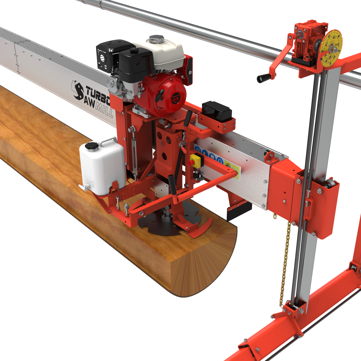
Make the gaps at A and B match.
Blade horizontal · Power isolatedA = BCompare the gap from the tooth tip to the timber face at A and B. Aim for equal gaps, with no more than 0.25 mm (0.010 in) difference.
- Look at A and B.
- Use the lettered positions in the picture. Measure at the tooth tips, not the flat steel body of the blade. The 0.25 mm (0.010 in) tolerance is the difference between the two gaps, not a target clearance for each one.
- Move the bearing up or down.
- Loosen the main M16 bearing bolts enough to permit adjustment. Use the M10 setscrews to move the bearing within its slotted mount.
Bearing UP ↑Position B rises.Bearing DOWN ↓Position B lowers.- Lock it, then check again.
- Secure the bearing bolts to your model's requirements. Recheck A and B after tightening; do not assume the setting stayed exactly where it was.
Tool tip for the illustrated assembly: hold the bearing-side nut with an open spanner and turn the inner bolt with a 24 mm (0.945 in) socket or ring spanner. The inch equivalent describes the size; use the specified metric socket or spanner.
Check before moving on
A and B match within 0.25 mm (0.010 in), and the bearing bolts are locked. Leave this adjustment alone while setting the lead-in.
Next: Adjustment 2 →
Top: compare the tooth-to-timber gaps at A and B. Bottom: the arrows identify the bearing adjustment area.
Enlarge Adjustment 1 ↗ -
Adjustment 2 / Horizontal lead-in
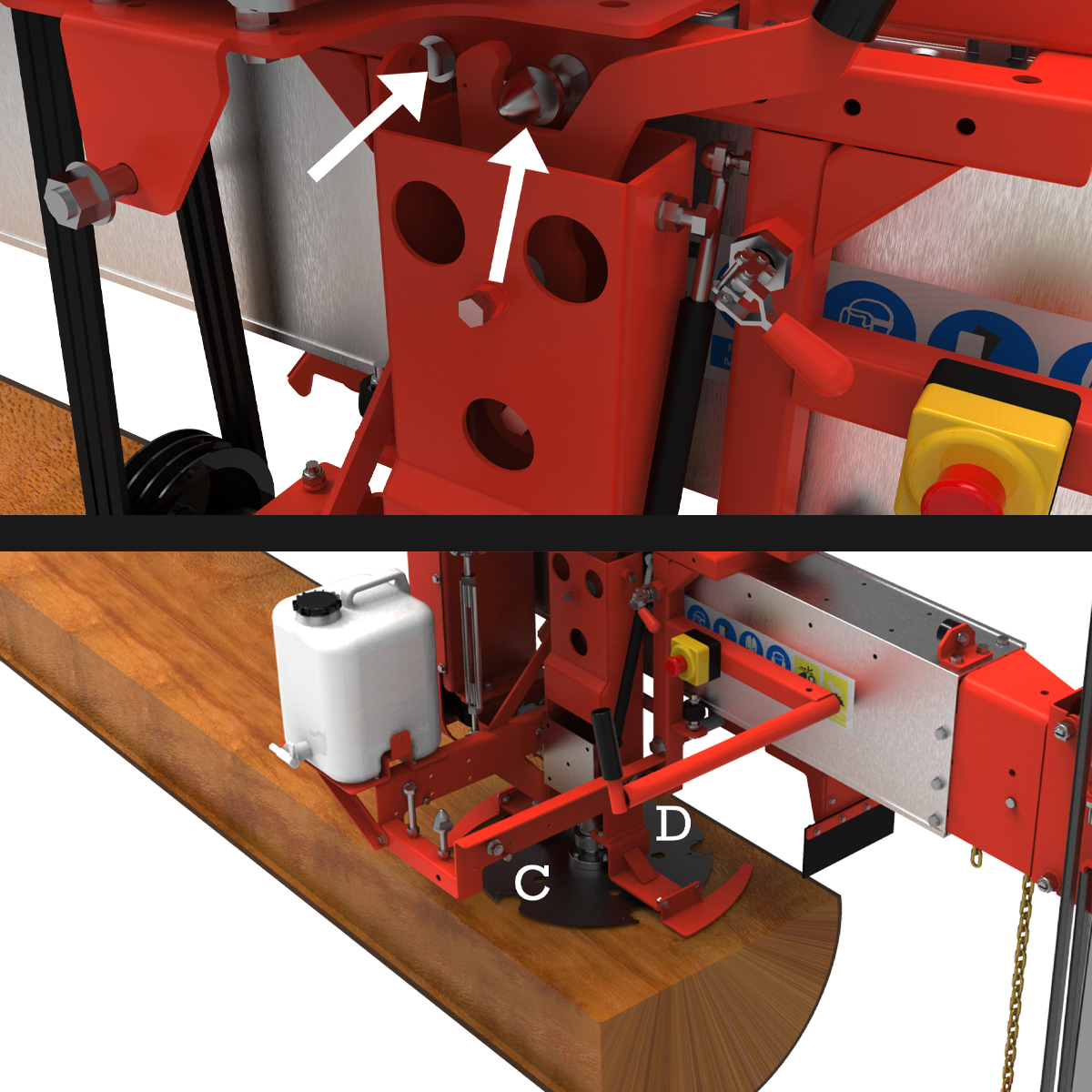
D just touches. C has clearance.
Blade horizontal · Power isolatedD: just touching
C: 2–4 mm (0.08–0.16 in) clearThe gap at C is approximately 2–4 mm (0.08–0.16 in). Unlike Adjustment 1, these two gaps are not supposed to match.
- Check the two labelled positions.
- At D, the stationary tooth should only just touch the skimmed face—not be pressed into it. At C, check for 2–4 mm (0.08–0.16 in) of clearance. This deliberate difference is the horizontal lead-in.
- Adjust the horizontal swing-stop.
- Find the M12 stopper beside the cone lock. Depending on the fitted version, the setting uses washers or the hex adjustment nut behind the stopper. On the screw-adjusted version, screwing the M12 stopper in increases the gap at C.
- Reset the cone lock.
- After moving the stopper, readjust the adjacent cone so the swing arm locks firmly with no free movement. Recheck C and D with the lock secured.
Check before moving on
D just touches, C is 2–4 mm (0.08–0.16 in) clear, and the swing arm is locked without play. Do not try to make C and D equal.
Next: Adjustment 3 →
Top: stopper and cone-lock locations. Bottom: C needs clearance while D just meets the face.
Enlarge Adjustment 2 ↗ -
Adjustment 3 / Vertical criss-cross alignment
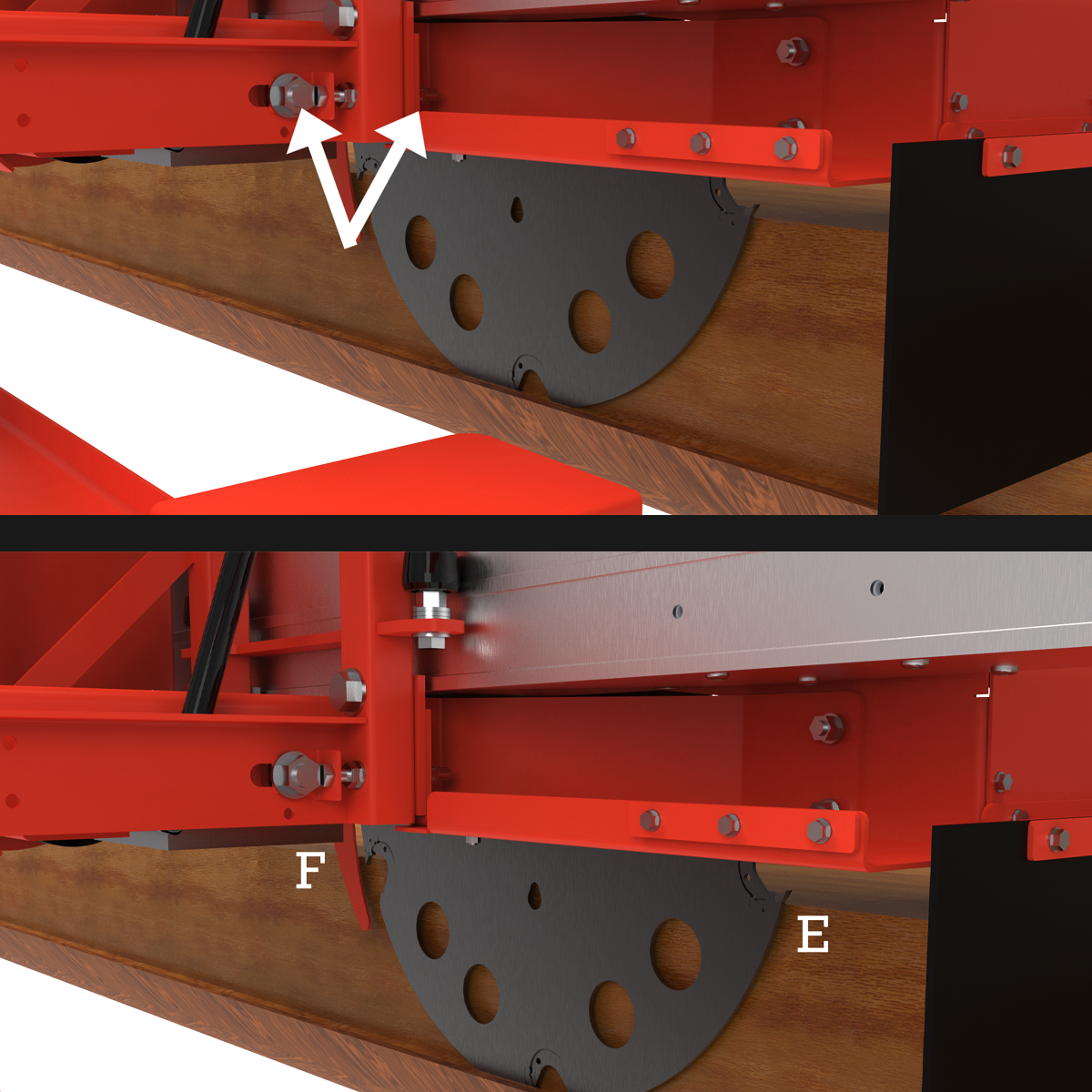
Make the gaps at E and F match.
Blade vertical · Isolate before checkingE = FCompare tooth clearance against a freshly cut vertical face. Aim for equal gaps, with no more than 0.25 mm (0.010 in) difference.
- Make the vertical reference face.
- Leave Adjustments 1 and 2 locked. Refit the guards, clear tools and make a vertical cut down the far-left edge of the log, within your model's cutting capacity and with water flowing. A light, slow re-skim may be needed for a clean reference.
- Stop, isolate and compare.
- Wait for the blade to stop and isolate the machine again. Position the vertical blade alongside the new face. Compare the tooth-to-face gaps at E and F.
- Move the pivot sideways.
- Loosen the single large M16 nut. Use the M10 setscrew to shift the axis bush—the pivot bush—and its M16 nut left or right in the slot.
Bush LEFT ←Position E moves left.Bush RIGHT →Position E moves right.Directions follow the illustrated assembly. Identify E and F on the picture before making a small adjustment.
Lock and check before moving on
Secure the nut and adjustment fasteners, then recheck E and F. They must match within 0.25 mm (0.010 in) after locking.
Next: Adjustment 4 →
Top: the pivot adjustment in its slot. Bottom: compare E and F against the new vertical face.
Enlarge Adjustment 3 ↗ -
Adjustment 4 / Vertical intersect
Make the two cuts meet cleanly.
Test cut guarded · Adjust with power isolatedBoard releases.
No unwanted scoring.The horizontal and vertical cuts must meet so the board separates. The vertical blade should not unnecessarily score the timber face below it.
With Adjustments 1–3 locked and guards refitted, make a test board. Stop and isolate before inspecting the cut or moving the adjuster. Do not pull at a trapped board while the saw is running.
Board still attached?
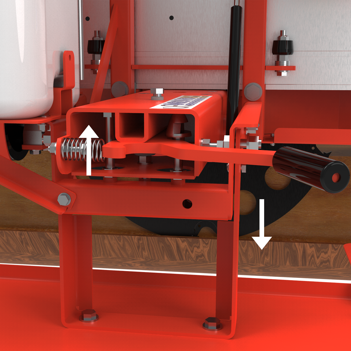
The cuts may not be meeting. Raise the long M12 vertical stopper slightly. This lowers the vertical blade. Readjust the cone to lock securely, then make another guarded test cut.
Board releases, but the blade marks the face?
Lower the long M12 stopper and its locking cone. This raises the blade slightly away from the timber face. Secure the lock and test again.
Stopper UP ↑Vertical blade DOWN ↓Stopper DOWN ↓Vertical blade UP ↑Move only as far as needed. The original procedure describes typical stopper corrections of about 1–3 mm (0.04–0.12 in), not a fixed amount to add on every attempt.
The direction is easy to mix up: raising the stopper lowers the blade.
Enlarge Adjustment 4 ↗Final static clearance check
Skim the top face with the saw guarded. Stop and isolate. Following your model's safe positioning procedure, swing the blade to vertical and position it over that freshly skimmed face.
For the illustrated setup, the bottom tooth should sit approximately 3 mm (0.12 in) above the skimmed face in this checking position.
This is a clearance measurement in the stated check position—not a 3 mm (0.12 in) uncut bridge to leave in a board. Confirm the finished setting with a guarded test cut and clean board release.
Adjustment 4 is complete when
The board releases cleanly, unwanted vertical scoring is removed, and the stopper and cone lock are secure. Changing an earlier adjustment now means rechecking the later ones.
The sequence, at a glance
Match. Lead-in. Match. Intersect.
- 1 / HORIZONTAL
- A = B.
Difference no more than 0.25 mm (0.010 in). - 2 / LEAD-IN
- D just touches.
C is 2–4 mm (0.08–0.16 in) clear. - 3 / VERTICAL
- E = F.
Difference no more than 0.25 mm (0.010 in). - 4 / INTERSECT
- Cuts meet cleanly.
Board releases without unwanted scoring.
Before returning to work: secure all adjustment fasteners and swing locks, remove tools, refit guards, check the work area is clear and make a controlled test cut using the normal operating procedure.
Still not right? Do not start moving random screws. Recheck the sequence, log support and blade condition. Get model-specific help if a setting will not hold or the result remains wrong.
After the four adjustments
Other things that affect your cut.
These are operating and maintenance topics—not extra blade-alignment adjustments. Open the topic you need after completing the four-step setup.
Log support: stop sagging and movement
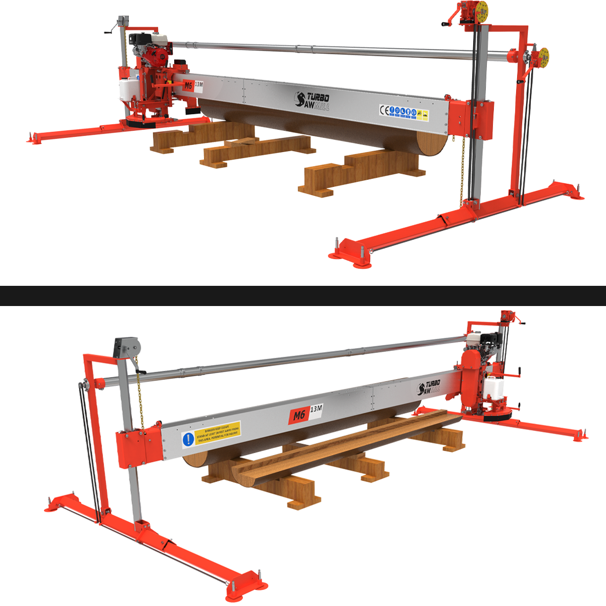
Bunks are the supports beneath the log. The illustrated arrangement uses two main timber bunks and a smaller middle support, with opposing wedges for fine support at the centre.
Support the log along its working length and restrain it against rolling. Check support as timber is removed; an unsupported remainder can move and change board thickness even when the blade settings are correct.
Keep bunks, wedges and fasteners outside the intended blade path. Stop and isolate before changing supports, and keep the operator's walkway clear.
Enlarge the support illustration ↗
Horizontal bounce: reduce the cutting load first
A wide horizontal cut may need more than one pass. Reduce the initial bite rather than forcing a full-width cut through difficult timber. Check blade sharpness, feed rate and the four settings first.
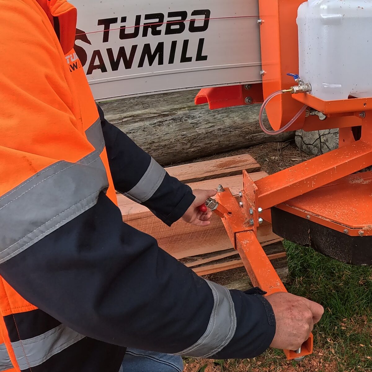
Where fitted, set the horizontal guard's side roller according to the manual to support the cut. Stop and isolate before adjusting the roller or its locking knob.
Powered return or bridge-cutting techniques are model-specific. Use only the method approved for your machine and training; do not transfer powered-feed techniques to a manual mill. Use only approved stabilisers or centre-leg arrangements, and do not improvise guard modifications.
Enlarge the stabiliser photograph ↗
Resawing: straightening an oversized board
Resawing means cutting an existing board again. An oversized board with uneven edges or movement may still contain a useful straight piece. Leave enough allowance in the original dimensions for the extra cut.
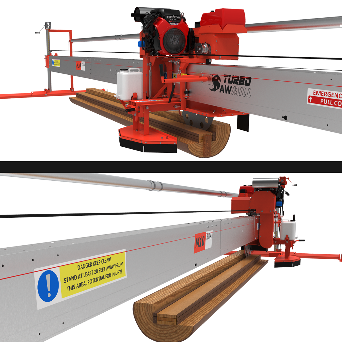
The illustration shows edging and thicknessing arrangements using a stable support surface. Use your model's approved supports, stops and restraints. Do not rely on your hands or cutting force to hold loose timber in place.
Keep hands clear of the blade and confirm that all restraint hardware is outside the cutting path. The picture explains the arrangement; the operating manual supplies the working procedure.
Enlarge the resawing illustration ↗
Kerf and cutting patterns: plan the boards inside the log
Kerf is the width of timber removed by the blade. Your sizing and cutting plan need to allow for it. The original diagram compares example board layouts using different kerf widths.
The layouts are examples, not a promise that different blades always recover the same amount of timber. Log diameter, target board sizes, defects and the cutting pattern all affect the result.
Quarter sawing and flat sawing describe board orientation relative to the log's growth rings. Choose the pattern for your timber and intended product, then work through the log with adequate support.
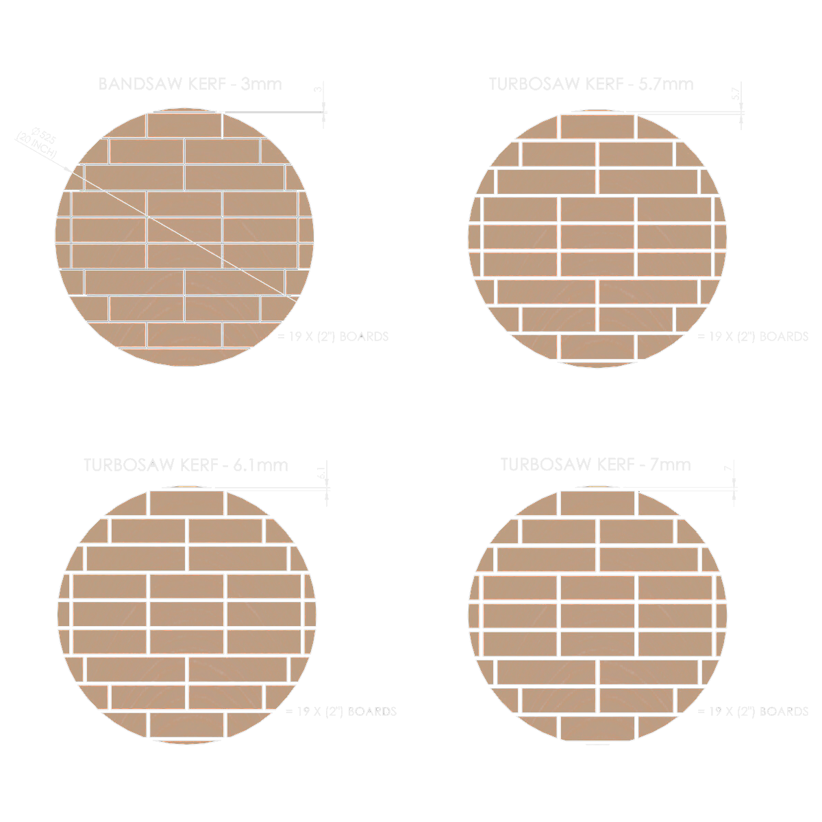
Kerf widths shown: 3 mm (0.12 in), 5.7 mm (0.224 in), 6.1 mm (0.240 in) and 7 mm (0.276 in).
Enlarge the kerf comparison ↗
Blade condition: check this before changing the alignment again
A dull or damaged blade and worn or loose components can affect the cut. Stop and isolate before inspection. Use the sharpening, tooth-replacement and blade-servicing procedures for the blade actually fitted to your sawmill.
Do not try to compensate for damage or a loose assembly by changing the four alignment settings. Correct the underlying fault first, then recheck the adjustment sequence.
Model-specific technical support
Tell us which step is not right.
Send your model and serial number, a clear photo of the relevant adjuster, and the gaps you measured. Tell us whether the problem is at A/B, C/D, E/F or the final intersect. That gives us a useful starting point without changing everything at once.
Contact Turbosawmill support →Illustrations show a particular Turbosawmill assembly and may differ from your model. Use the current operating manual for isolation, guarding, safe positioning, fastener requirements and model-specific settings. The four-step sequence does not replace operator training or a complete safety procedure.
TRAINING
HELPFUL VIDEOS
A collection of helpful videos covering a range of practical sawmilling topics, including how to saw small logs, quarter sawing, adjusting your mill, improving your cutting technique, and a number of other useful operational tips.
Whether you are new to swing-blade sawmilling or looking to refine your technique, these videos are designed to make the machine easier to understand and help you get the best from your Turbosawmill.
ADJUSTING YOUR TURBOSAWMILL
This tutorial video takes you through the four steps required to correctly adjust your sawmill blade. The same adjustment sequence applies across all three current Turbosawmill models, making it a useful reference whenever you need to check or reset your blade alignment.
Follow the steps in order, as each adjustment affects the next.
SECTION SAWING ADVANTAGE
This video explains the efficiency and advantages of sectional horizontal cutting.
By dividing a wide horizontal cut into smaller sections, you can improve cutting accuracy, reduce the load on the blade, and make the overall cut more efficient.
Another advantage is the type of waste produced. Instead of creating fine sawdust, sectional cutting can produce larger chips or slivers, giving you a different and potentially more useful by-product from the milling process.
ASSEMBLING YOUR WARRIOR MANUAL MILL
This video shows the process of hand-carrying and assembling an M10 around the log when you are not using transport options such as jockey wheels or ATV wheels.
It is an earlier video showing the mill with a 13 hp engine. The current engine option is 25 hp, which is heavier and also includes a separate fuel tank, so allow for the additional weight when carrying and assembling the machine by hand.
SMALL LOGS WITH THE TURBOSAWMILL
This quick video demonstrates three different ways to saw small logs on the M12, showing just how flexible the swing-blade concept can be.
Depending on the log and the timber you want to produce, you can approach the cutting sequence in different ways. In some situations, you can edge most of the log first and then release the finished section with a single final cut.
That can help reduce unnecessary movement in the timber during the process, particularly where internal stress may otherwise cause the log or boards to move or deform as material is removed.
SMALL LOGS USING GROUND BUNKS
This video shows the basic principle of milling small logs by cradling them securely in notched bunks positioned on the ground.
It is a simple, practical setup that keeps the log supported while you work through the cutting sequence, and gives a good overview of the general process of using a swing-blade sawmill on smaller-diameter logs.
HARDWOOD BEAMS
This is a very early video showing the process of milling large beams from hardwood logs using the M12.
It demonstrates the basic swing-blade cutting sequence and how the machine can work through dense hardwood to produce accurate, heavy structural beams directly from the log.
RELEASING A SEIZED BLADE SCREW
This video shows how to deal with a locked blade screw. Once you know the correct method, it is quite straightforward to remove.
It also highlights the importance of applying anti-seize to the screw heads before installing the blade. This helps prevent the fasteners from binding or seizing over time and makes future blade removal and maintenance much easier.
SWITCHING TEETH ON THE TURBOSAWMILL
This video shows how to replace the insert teeth on a Turbosawmill blade without removing the blade from the mill.
The process is straightforward: punch through the small grub screws that retain the insert, then use the hand tool to cam the worn tooth out and fit the replacement.
Because the work can be carried out with the blade still mounted on the sawmill, routine tooth replacement is quick and convenient.
PRICE YOUR SAWMILL
need pricing?
click the link below
Select your mill with accessories, delivery and training.